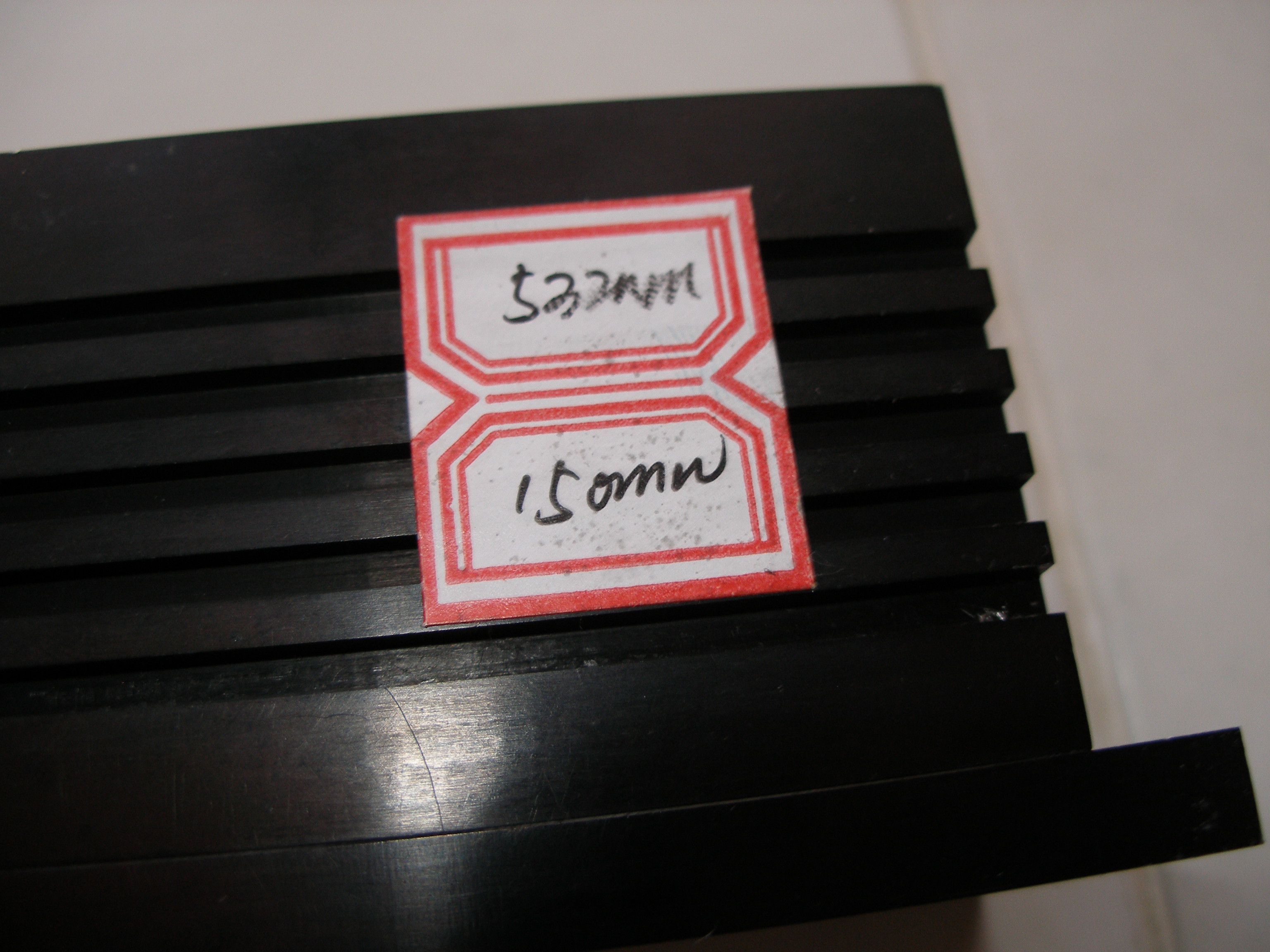
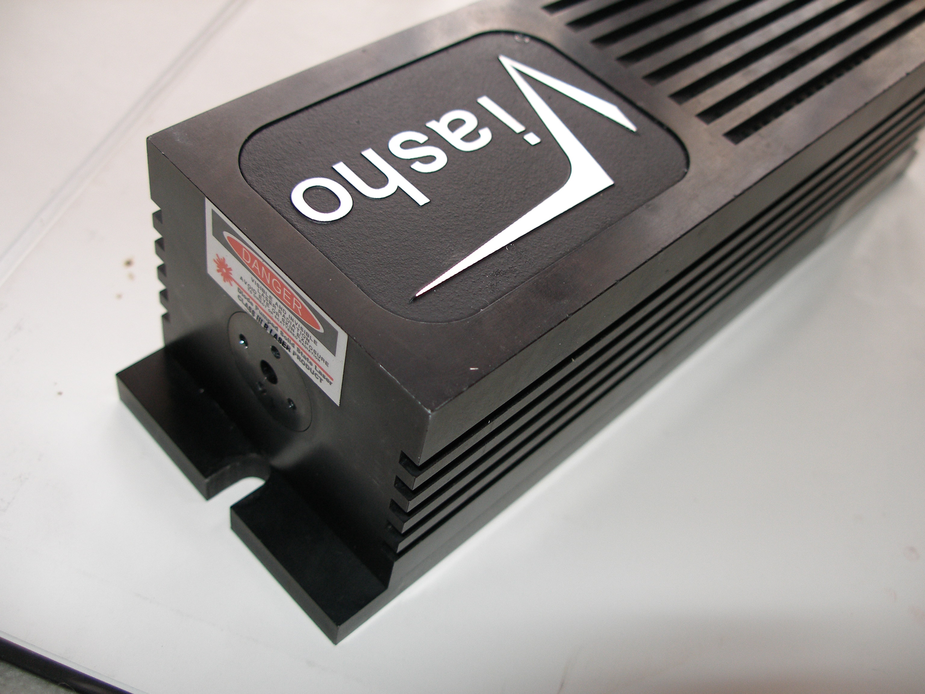
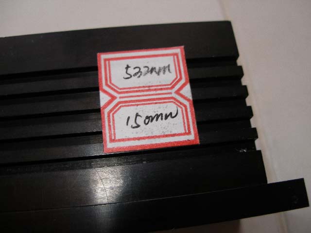
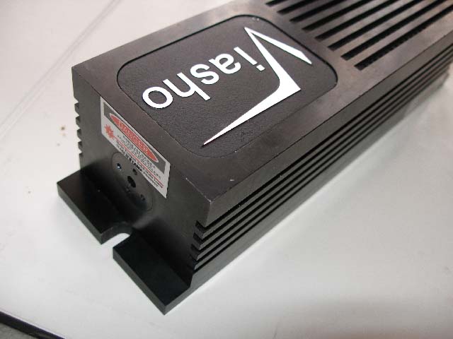
Viasho VB-150, 150mW, 532nm, TTL modulation.
Last Update: 1.december 2007
Disclaimer:
Any
information provided on this site is not guaranteed in any way. All
informations here are provided for
educational purposes only, USE THEM AT YOUR OWN RISK ! If you blow up your galvos, home, computer,
or anything else -- it's not my fault, use good judgement and play nice.
I bought this laser head aproximately 2 years ago (in may 2004). After
two years power has decreased and beam changed its shape.
Originaly it was working in TEM00. I'm sure I didn't reach "life time" of the laser diode (5000 hours).
Beam cross section was like this (illustration picture):

TEM00
Now I have beam cross section like this (output power has also decreased) = split beam (illustration picture):
TEM01
I don't have power meter. You ask me, how I know that power has decreased ? Maybe you will laugh, but it was quite simple.
When the laser head was new and has TEM00, it can fire up a safety match in few seconds. Now (TEM01) it cannot fire up the
safety match :-) thus I think power has decreased.
So I was thinking to open the laser head to check following:
1. What is "stand-by current" of laser diode (treshold or biasing
current = current through laser diode just before it starts to lase).
On different laser unit (Medialas DPGL 50 A) stand-by current was set to 60mA (laser OFF).
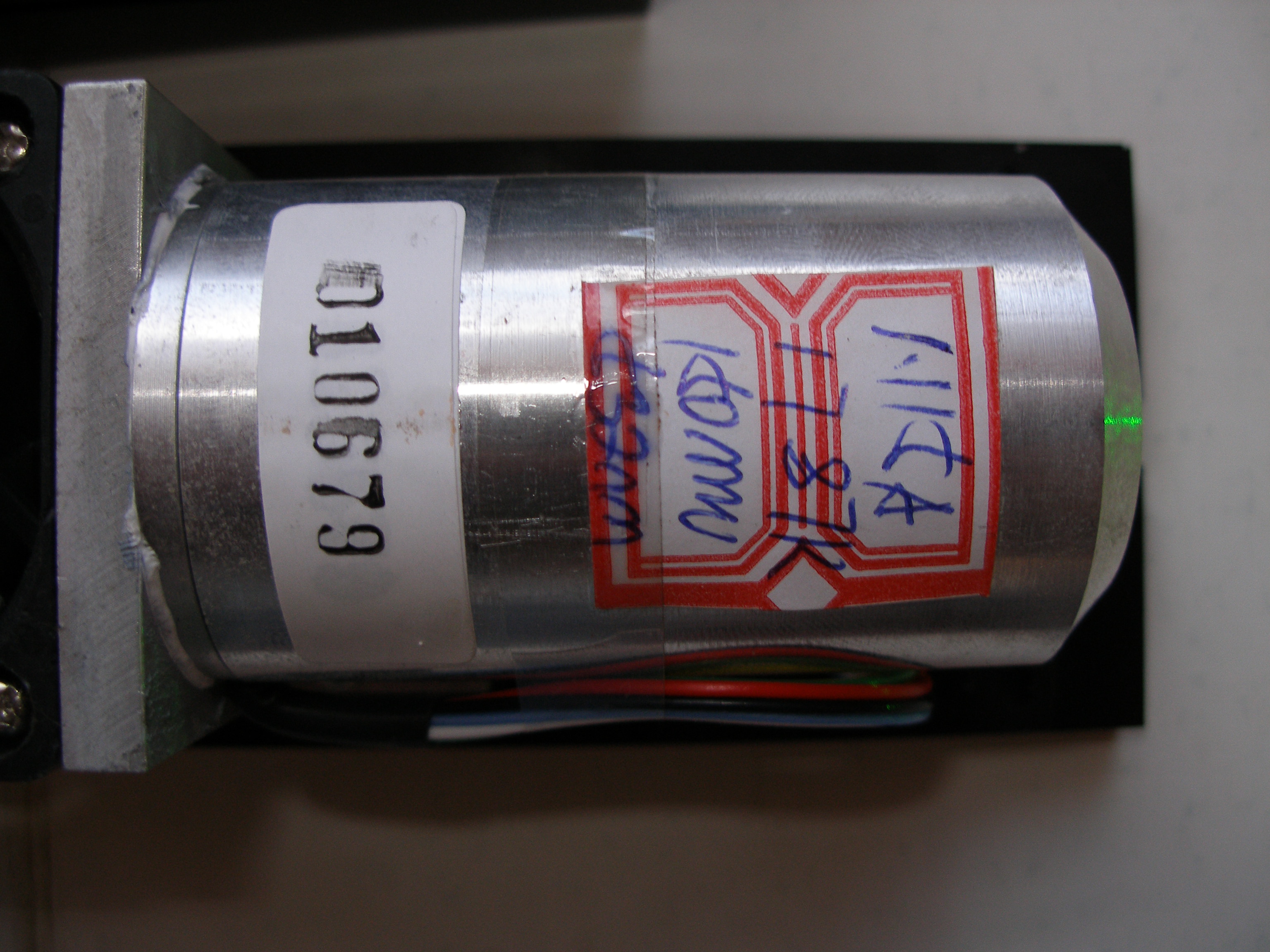
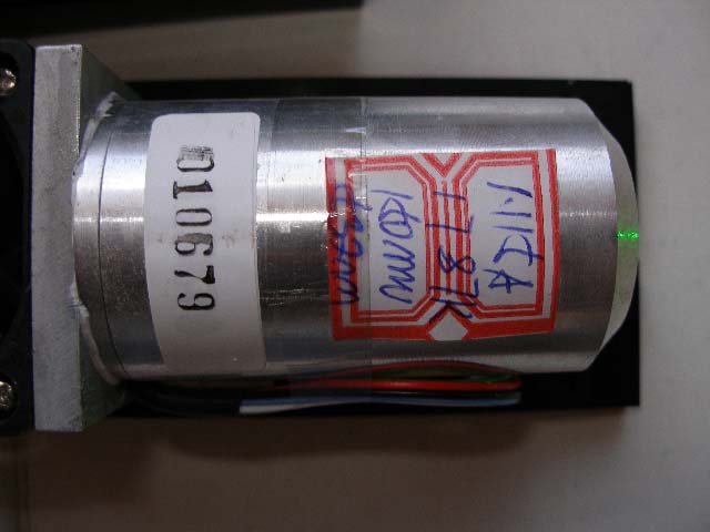
2. What is the operating current during full power (laser ON). On picture 10 is written 1.115A, so I think this is the wanted
value of the operating current.
3. What is voltage across temperature sensing thermistor(s) when the laser is OFF and ON.
On picture 10 is also written 17.87K. I think it is the
resistance of the thermistor at the wanted operating point of the laser
diode.
4. If TEC is working correctly. Voltage across it's terminals.
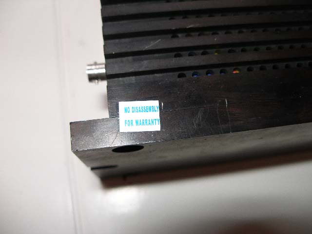
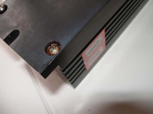
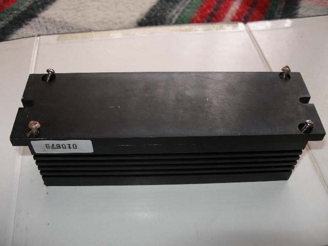
This laser head was never opened (dismounted) before, I opened it after warranty period has gone.
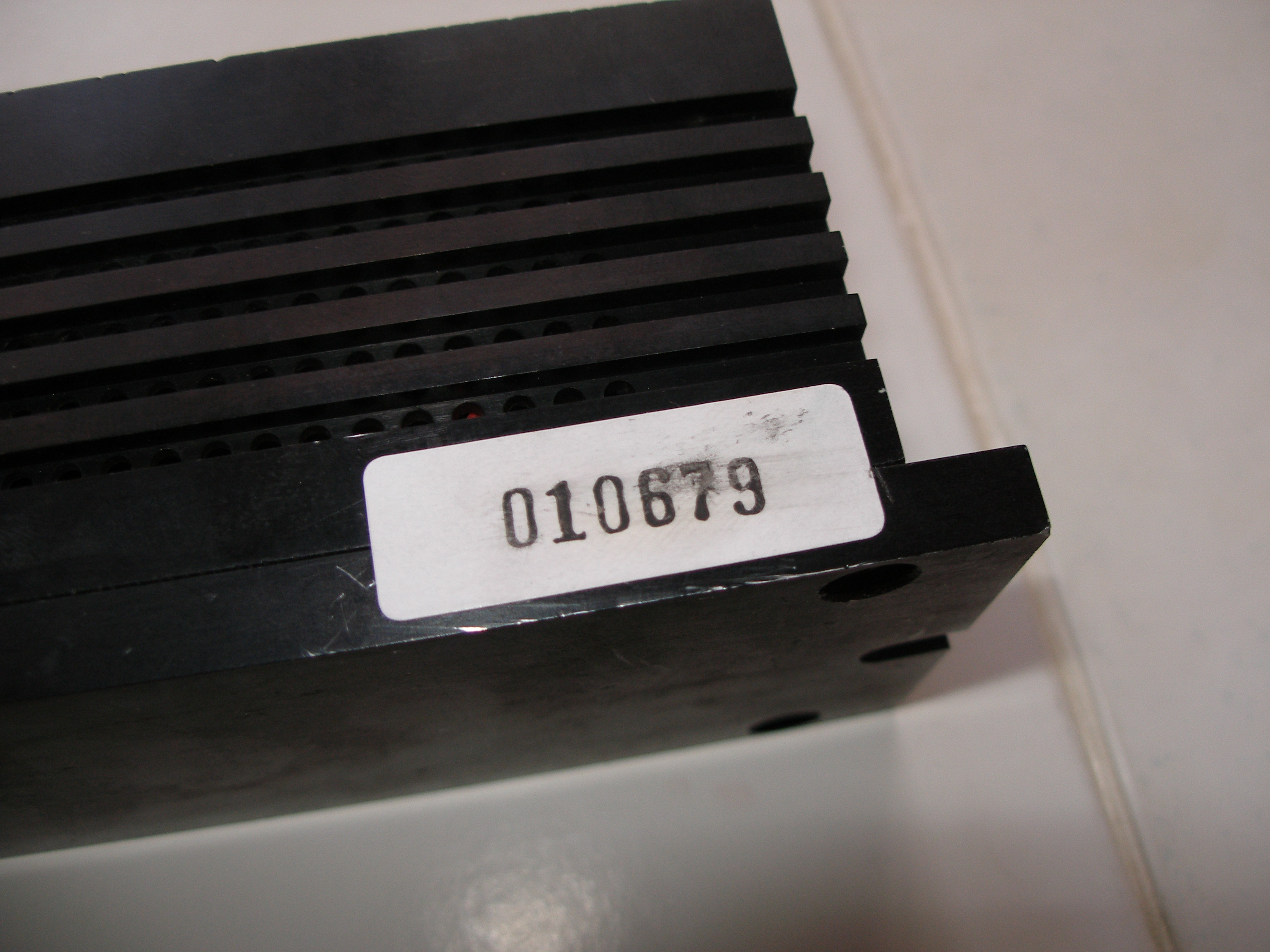
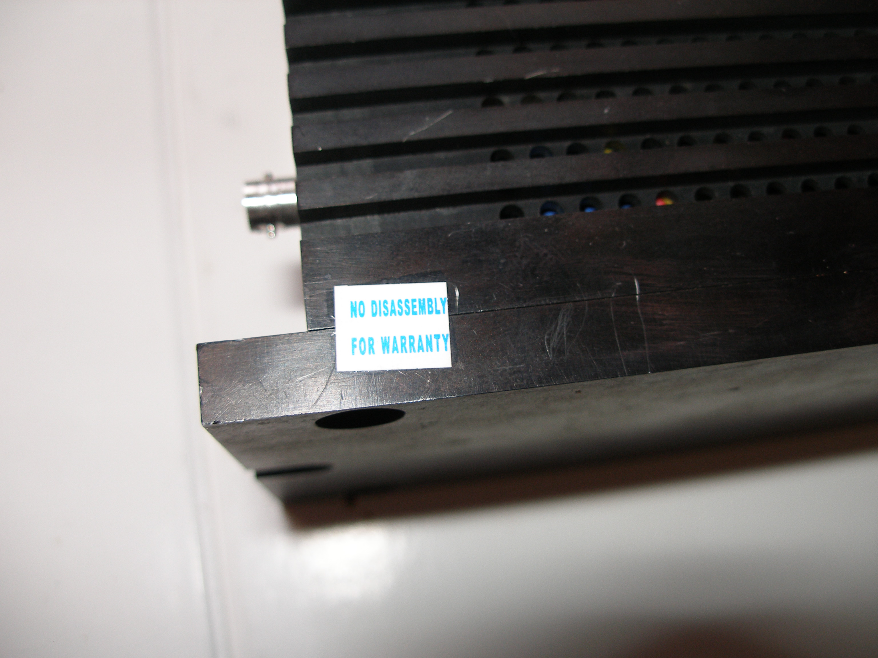
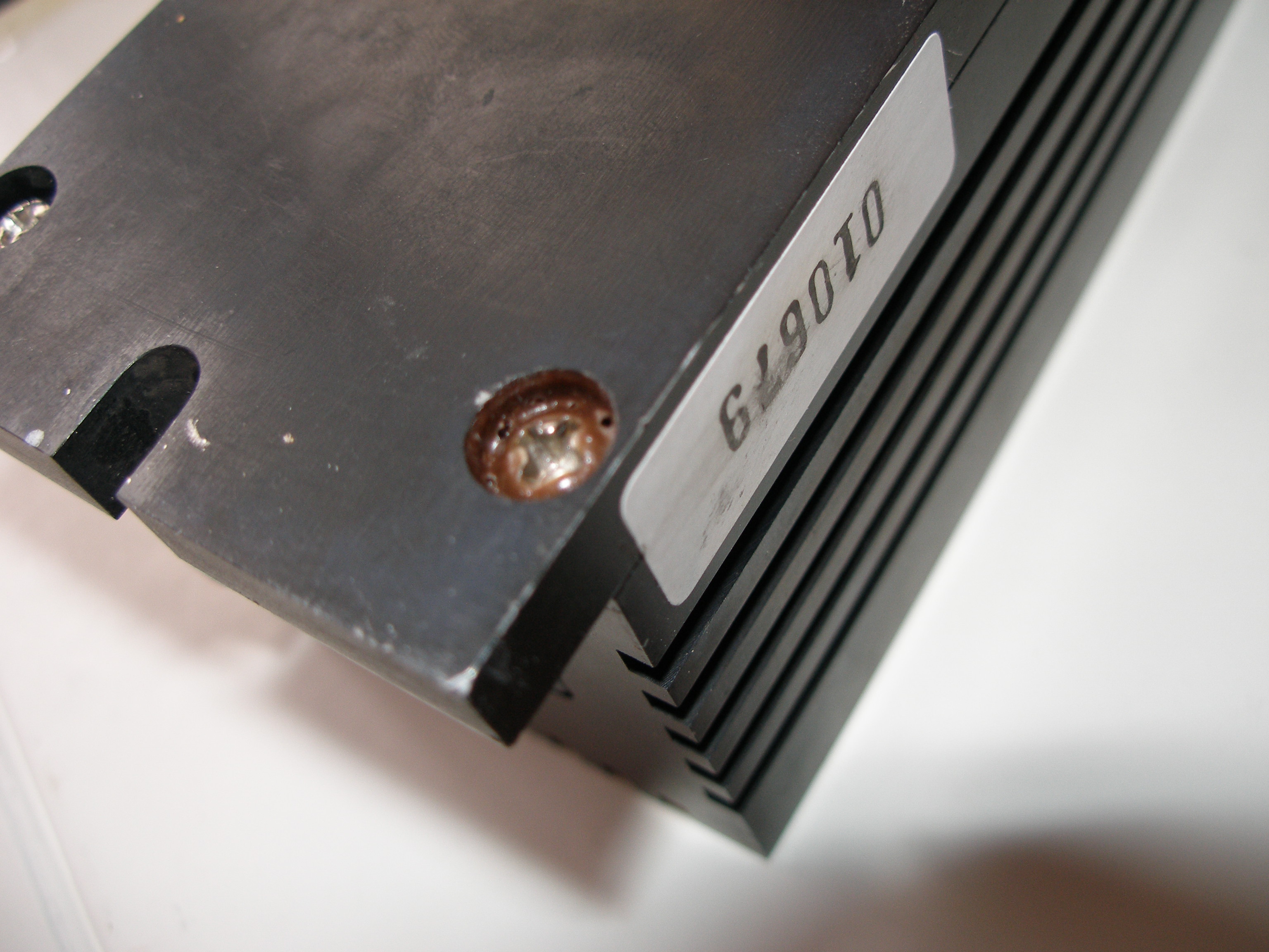
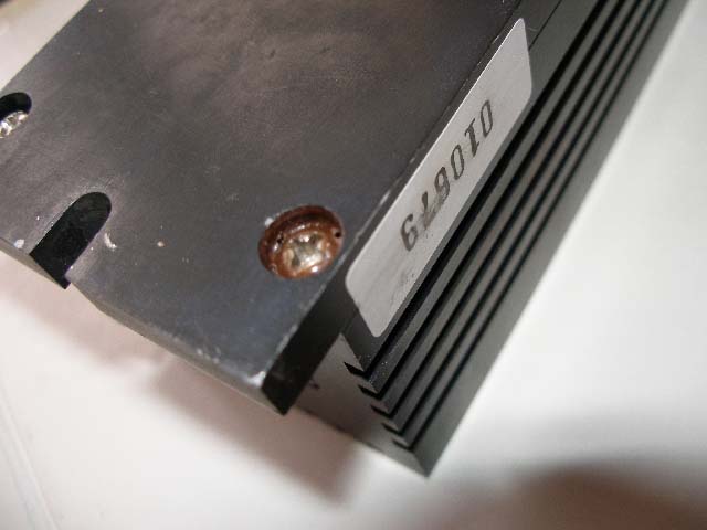
It can be seen on pictures 1 to 7 that warranty label was on original position. Also serial number
label was on its original position. Two of bottom screws were glued.
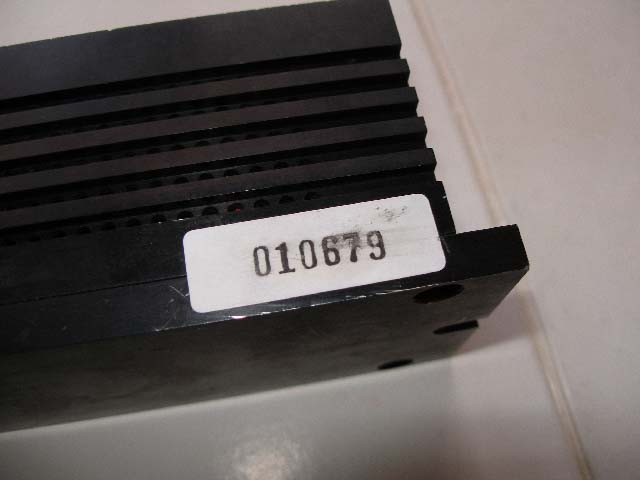
Picture 1
Picture 2
Picture
3
Picture 4
Picture 5
Picture 6
Picture 7
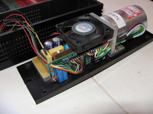
Laser head was opened today 26.november 2007:
Picture 8
Picture
9
Picture 10
Picture 11
Picture 12
26.november 2007
Measurements:
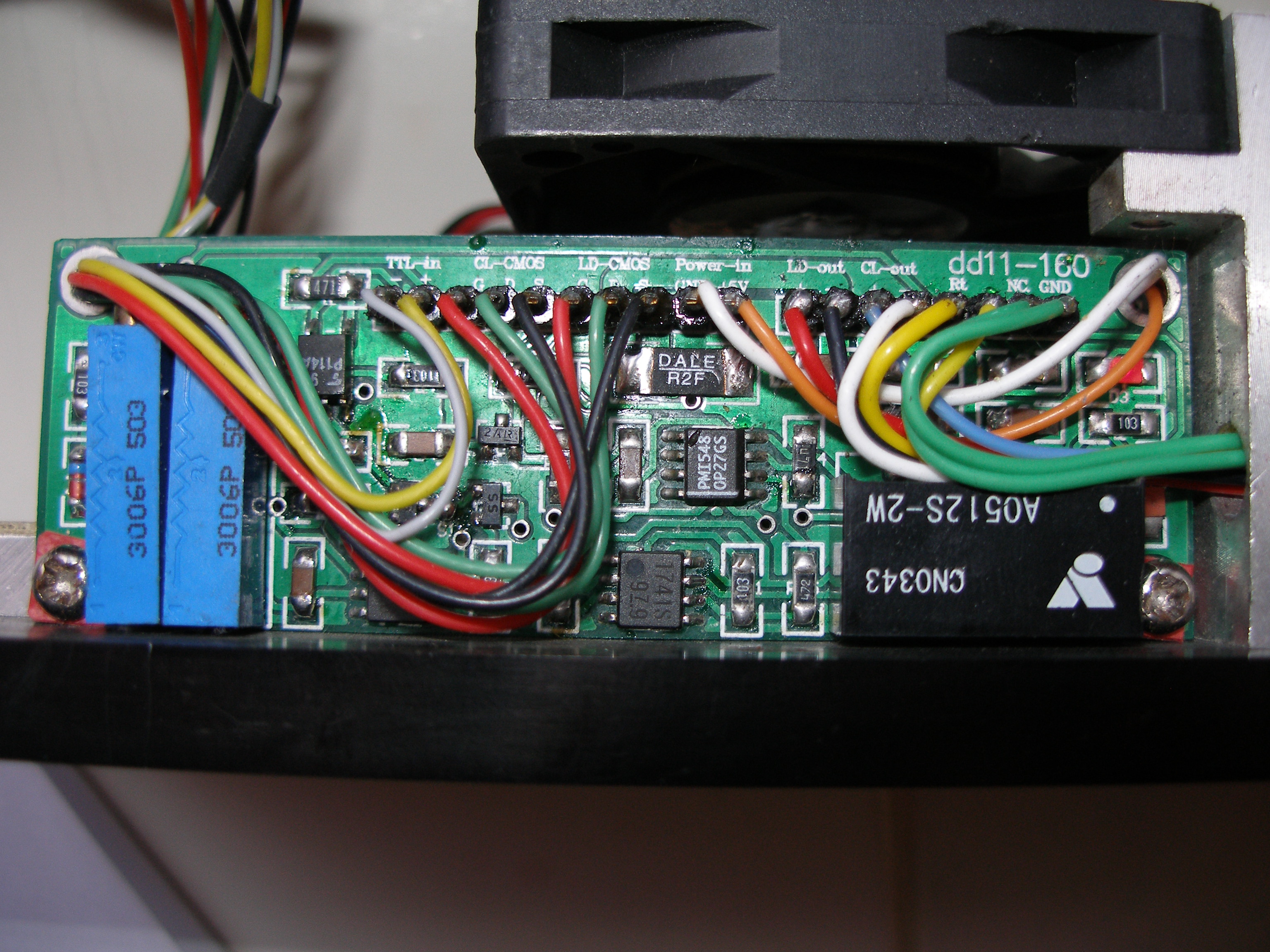
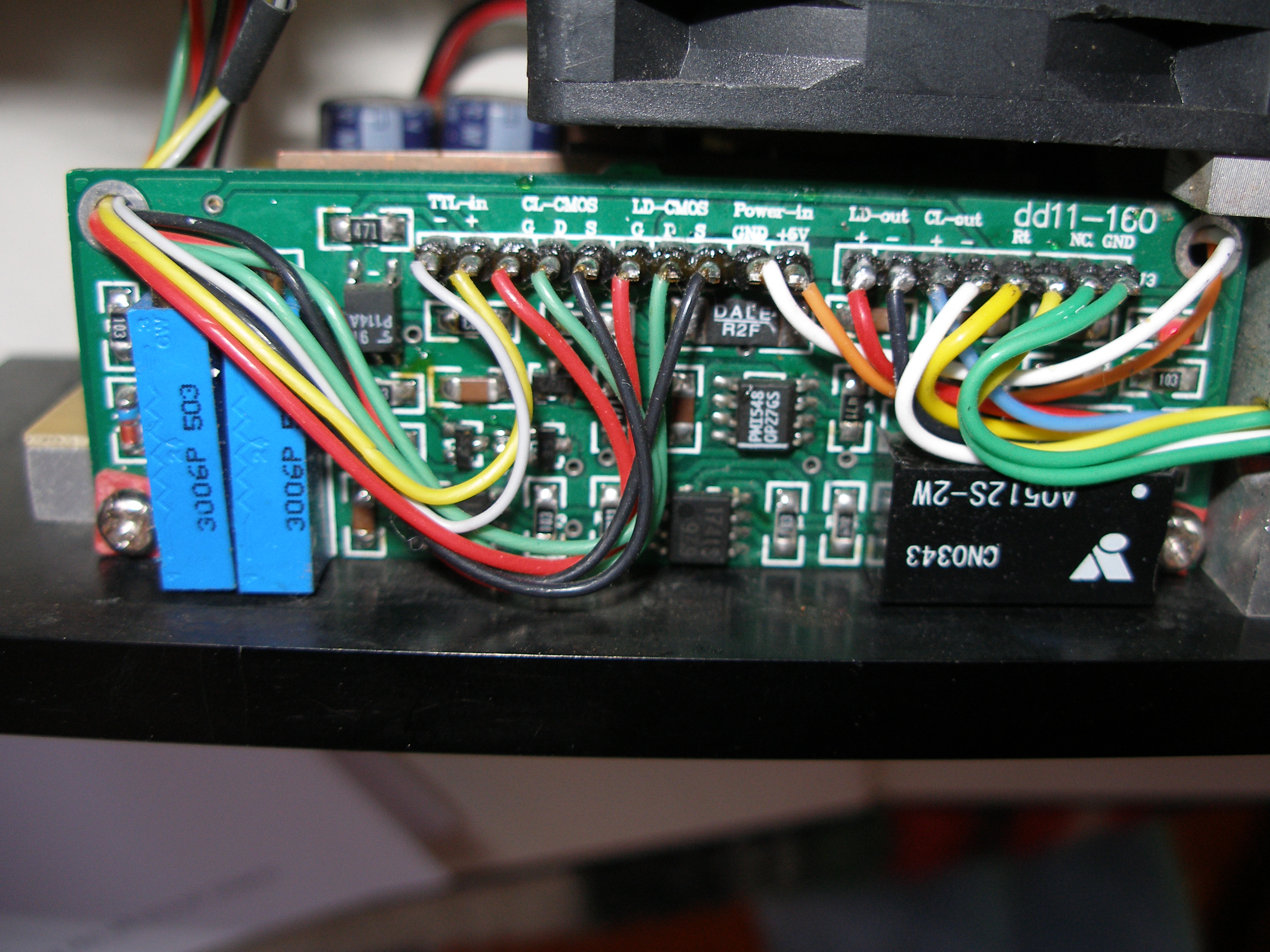
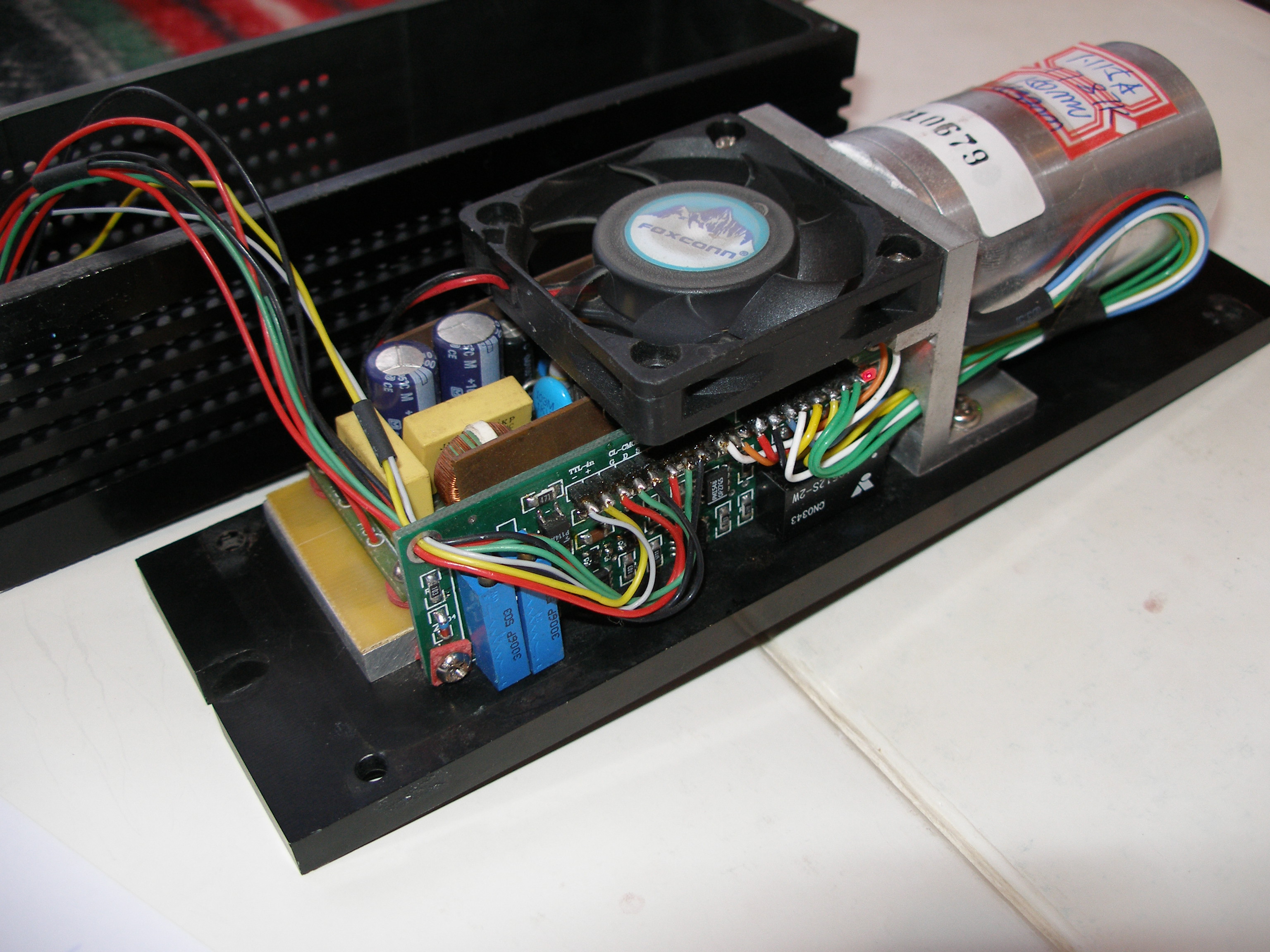
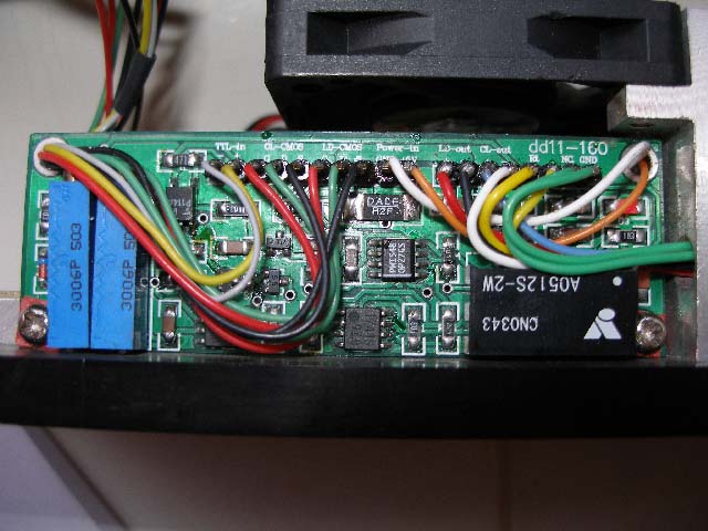
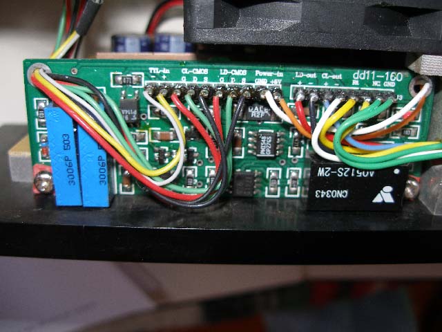
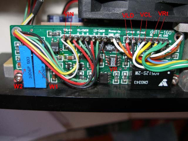
I measured DC voltages as it is stated on the following picture (Measurement 1).
On PCB all terminals are marked so I think I correctly identified all of them.

Measurement 1
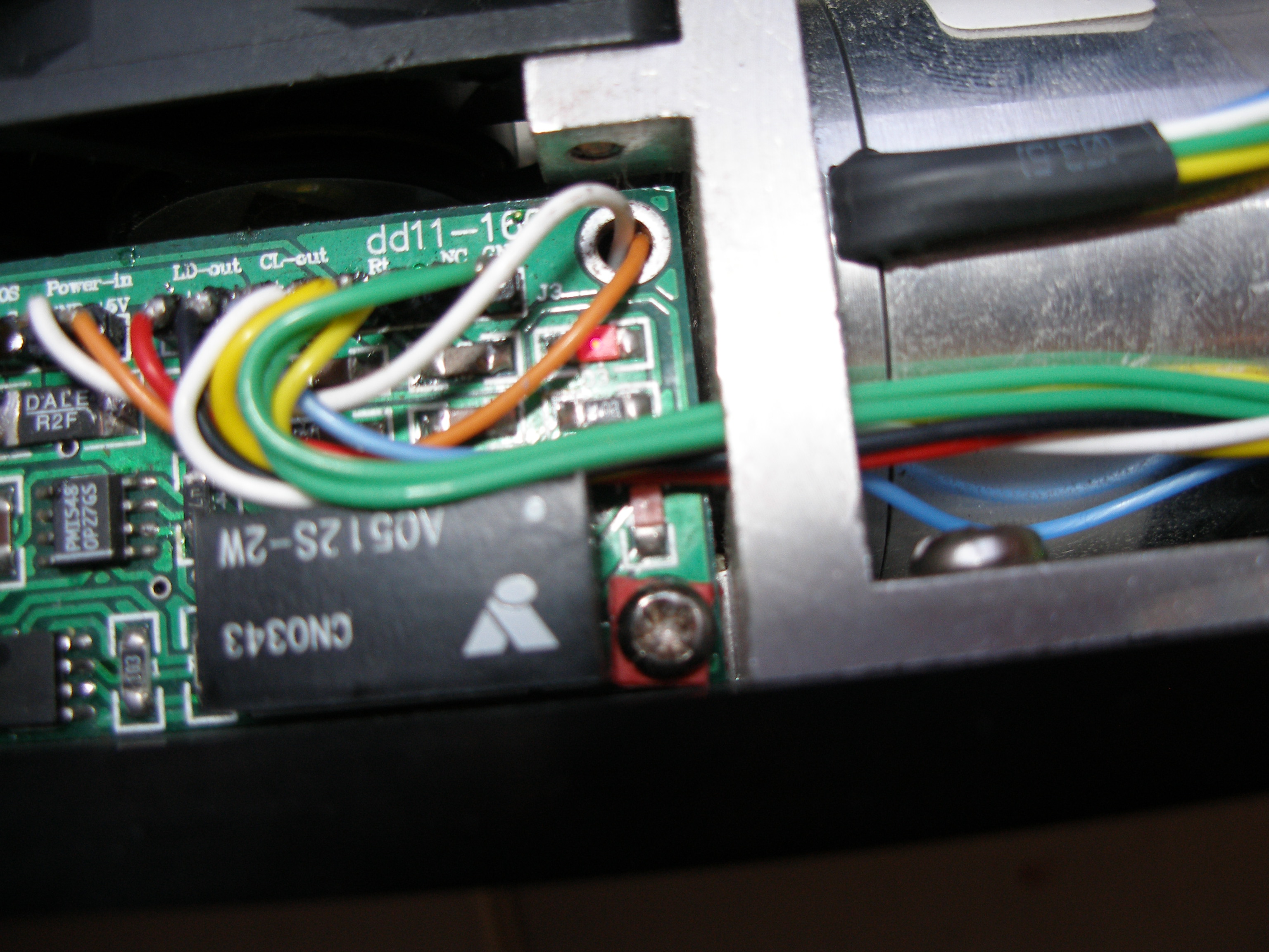
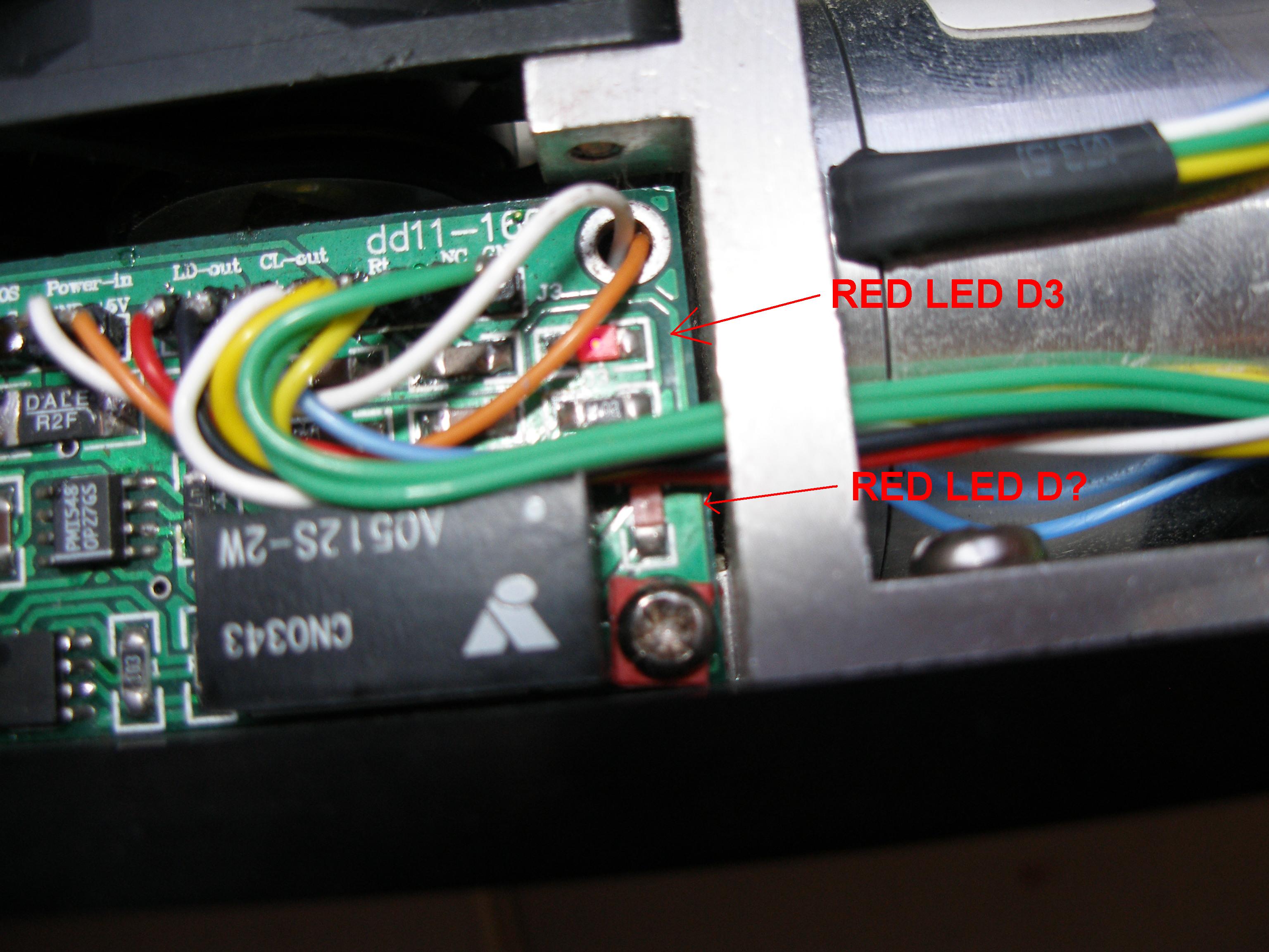
Measurement 2
VIN = input voltage (from modulation input), 5V laser fully ON, 0V laser fully OFF.
VLD = voltage across laser diode terminals (probaly makes no sense to measure because diode is current operated).
VCL = voltage across TEC ( I think TEC is connected here, on PCB it is marked CL-OUT).
VRT = voltage across thermistor which measures temperature of laser diode.
VR = on this resistor current through laser diode is measured. VR was 0V when laser was OFF. VR was 0.2151V whe it was ON.
So I think I identified it correctly. Value is 0.2 Ohm I think.
On the left side on the "Measurement 1" picture two trimpots are placed. I was told one is to set up laser diode current.
Second one to setup temperature of the laser diode. As marked in Measurement 1 picture: W2 controls current,
W1 controls temperature. On the picture "Measurement 2" two SMD LEDs can be seen. RED LED D3 is always ON.
RED LED D? was always OFF.
Laser head powered up, 5V DC connected to modulation input to have continuous operation (laser ON).
After 20 minutes this values were measured:
VIN= 4.99V , VR = 0.2151V , VCL = 0.194V , VLD = 1.858V , VRT = 4.153V
SMD LED D3 is ON, SMD LED D? is OFF
Question: Are these correct values ?
Then 5V DC was disconnected from modulation input (laser OFF):
After 30 minutes this values were measured:
VIN= 0V , VR =
0.001V , VCL = 0.037V , VLD = couldn't measure
stable DC voltage value , VRT = 5.72V
SMD LED D3 is ON, SMD LED D? is OFF
Question: Are these correct values ?
Questions:
1.
It looks
like laser diode has not stand-by (biasing) currnet set up. If there is
some biasing current,
I would
measure some voltage VR (if it is 60mA then VR= 60mA * 0,2 Ohm =
0.012V).
Is this
laser head operated with laser diode biased with some current ?
If
sensing resistor has 0.2 Ohm, then laser diode current during full
power is 0.2151 V / 0.2 Ohm = 1.0755A
which is
less then is written on picture 10 ( 1.115A ). Is this correct ?
I was told in case of 1W 808nm laser diode biasing (stand-by)
current is 200mA to 300mA. So in my case diode is
not correctly biased I think (no voltage across
the shunt resistor when the laser is OFF). I don't think there is
another
shunt resistor for biasing current. This is quite strange. Maybe there is
some problem in driver. If biasing
(stand-by) current should be 200mA to 300mA I should be
able to measure 0.04 to 0.06V across
shunt (0.2 Ohm resistor) when laser is OFF.
Answer: As this
is TTL modulated, laser head is probably operating without any
"stand-by" (treshold) current.
2.
What is
the temperature sensing termistor resistance at 0°C and/or at 25°C
? Is the VRT measurement correct ?
NTC thermistors are specified and/or referenced at 25°C.
I expect thermistor will have 10kOhm and is biased with cca
0.5mA. This current is low enough not to warm
thermistor and distort measurement accuracy. 10 K (25
°C) * 0.5mA produces 5V on it, I measured 4.153V during laser ON.
For NTC the higher
temperature, the lower the resistance thus lower voltage across it. This should be correct
because during laser OFF I measured VRT=5.72V (lower temperature
than during laser ON).
Answer: There is 20K thermistor inside biased with 0.2535mA (measurement is below).
Each thermistor type has
differen R-T characteristics. R-T curves ar not linear !
3.
Is TEC
operating correctly ? I think VCL = 0.194V DC during laser ON is too small
!
Answer: Based on feedback from Viasho engineers NOT !
4.
What is SMD LED DIODE D? used for ? It was always OFF !
( See Measurement 2 picture)
Answer: This indicates shutdown in case of failure.
5.
What is
the function of the FIRST trimpot from left side (Measurement 1
picture) ?
Answer: It is marked as W2, it is used to setup operating current. Turning it clockwise operating current is increased.
What is the function of the SECOND trimpot from
left side (Measurement 1 picture) ?
Answer: It is marked as W1, it is used to setup operating temperature. Turning it clockwise operating temperature is increased.
28.november 2007
Adjustments:
If you look on Picture 10 it is written on the label 1.115A , 17.87K.
This should be operating point of the laser head as it was setup
in factory.
At this operating point everything should be perfect ! Current can be
sensed on 0.2 Ohm SMD resistor which can be seen on picture Measurement
1 (VR voltage).
Temperature can be sensed on Rt terminals (two yellow wires, VRt voltage).
So how to check what is actual temperature ? Desolder one of the
yellow wires going to Rt terminals. Measure resistance between
this two yellow wire (one is desoldered now).
My reading is 21.64K (at the room temperature around 21°C). So I
assume there is 20K thermistor inside. Now connect amper meter between
desoldered yellow wire and terminal form which was the wire desoldered.
We will measure current through thermistor. This should be CONSTANT
value !
Turn laserhead on to full power. My reading is 0.2535mA. Turn the laser head OFF and solder back the yellow wire.
Now we can see that we have different temperature setup ! From factory
17.87K should be setup. From previous measurement we have 4.153V
at full power which is 16.38K (4.153V / 0.2353mA). This is HIGHER temperature than specified !
(Remember that thermistor is NTC, which means the higher temperature
the lower the resistance => the lower voltage on it when current
through 0.2535mA is constant ! )
Current through laser diode was measured before: 0.2151 V / 0.2 Ohm = 1.0755A, it should be 1.115A so we should measure VR = 0.223V.
So to go back to factory valueas specified on Picture 10. Turn Laser ON
to FULL power (CW). Measure VRt and turn W1 slowly counter-clockwise
to get VRt = 4.53V (with this we will lower operating temperature back to 17.87K).
Then measure VR voltage and turn W2 slowly clockwise. New VR value should be 0.223V which means 1.115A through laser diode.
I also measured VCL voltage, it was higher than before so I think TEC
was cooling down the laser diode more intensively (becuse lower
temperature was setup).
Then laser head was turned off for 30 minutes.
Then after 30 minutes I rechecked all values again and I have had
same results. I also measured total power consumption of laser head
at full power with these new setting. It was 12.7W ( 19.2VA) . It seems to me it is correct.
From all these new facts I feel that TEC is working correctly, because I was able to lower laser diode operating temperature.
Despite these new adjustment I still have split beam and lower power then before ! It looks like laser diode was damaged
due to overheating ! Why was the laser diode setup to differnet
operating point than it is on the label (Picture 10, 1.115A 17.87K ) ???
It could be that TEC was not 100% working or was partialy damaged
=> thus laser diode was operated at higher temperature 16.38K
and became also partialy damaged (split beam + lower output power).
1.december 2007
TEC cooling:
Some details how TEC cooling is working:
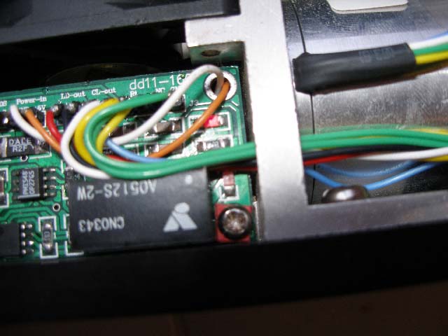
TEC output stage is according following picture:
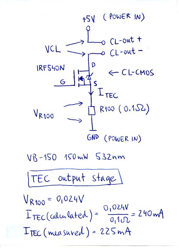
TEC is connected
betwenn CL-out+ and CL-out- terminals. Only cooling is possible !
When the laser is ON (CW) after 30 minutes this was measured:
Temperature is
stabilised VRt= 4.53V -> Rt=17.87kOhm.
VCL = 0.460V DC, ITEC = 0.225A DC,
and is stabile. Is not ITEC = 0.225A to small ?
No PWM used for TEC, only DC
current (ITEC) flows through TEC. This can be measured on the back side of
the PCB,
there is 0.1Ohm (R100) SMD resistor. Or it can be measured between
terminals (CL-CMOS S and POWER IN GND on Picture 8).
Please comment this if possible.
Main question is still the same: "Is this the reason for split beam and lower output power ?"
Answer: YES !
Regards
Stefan ( laserfreak at technoroam dot sk ).
Return